HallikainenAndFriends
Hallikainen And Friends
Though not a manual, this may be of interest nonetheless. During the development of the PCC-180 (see below), we experimented with an integer BASIC from Southwest Technical Products. We wanted the PCC-180 to be fully programmable by the user so the display, logging, and automatic actions could be set by the user through a user-supplied custom program. BASIC, being an interpreted language, seemed perfect for the application.
But, we needed a floating point version. Microsoft had a floating point BASIC interpreter. In December 1980, we licensed that interpreter for use in the PCC-180 (and later the DRC-190). The license calls for the source code to be delivered on 9-track tape, but we finally decided on 8 inch CP/M formatted floppy disk. We added a bunch of functions to the language (such as METER$, TIME$) and added code to interface to our hardware. The resulting image turned out to be about 16kBytes, 8kB from Microsoft, the remaining 8kB by me (Harold Hallikainen). Here's the original  Microsoft 8k BASIC license, dated December 10, 1980, and signed by William H. Gates, Partner.
 Remote Controls Have A History All Their Own - Radio World article by Tom Vernon on the history of transmitter control systems.
- Brochure describing program logging system, TVA series audio equipment, and TEL series telemetry.
- Company Profile, 1990
- Distributor Newsletter, December 1978 - Very slick marketing!
- Price List, April 1, 1978
- Price List, February 1, 1979
- Price List, July 1, 1981
- Photo Collection
DRC-190 Remote Control
- DRC-190 datasheet describes the system, all its options, and prices.
- Network Control of Subscriber Broadcast Transmitters - Describes the use of the DRC-190 by the Skylight Sattelite Network to control broadcast transmitters around the US.
Manual - Instruction manual on DRC190 (about 39 megabytes). The DRC190 is a multisite transmitter control system that allows up to 100 sites in a system. Each site may include analog inputs, control outputs, and status inputs. Each site includes a Basic interpreter and EIA232 port. Communications is over 2 or 4 wire circuits, including telephone line, subcarrier, and half duplex radio.
- Schematic
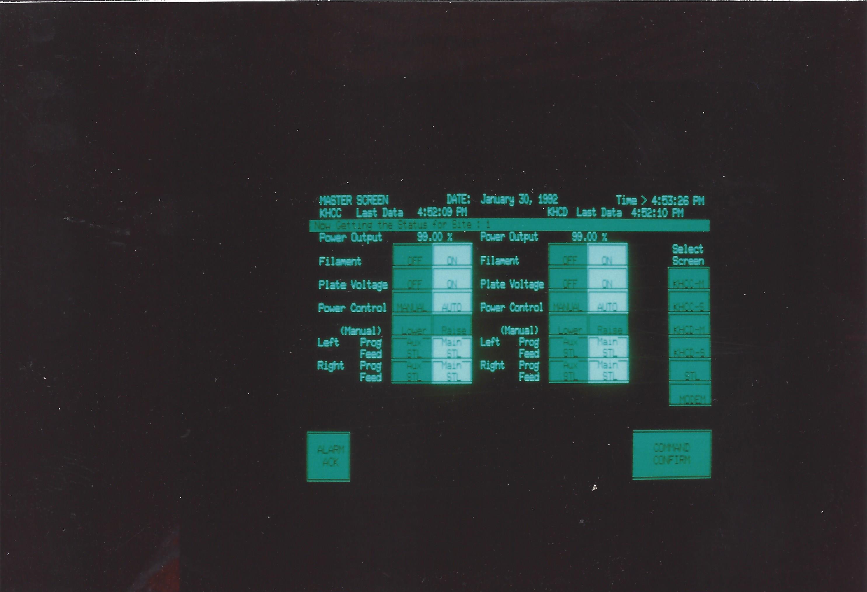
This photo shows the Fluke touch screen user interface for Radio Kansas. The DRC-1980 system controlled transmitter sites throughout Kansas. The Basic program running in the studio DRC-190 polled the transmitter sites and presented an overview page and individual pages for each transmitter site.
DRC-200 Remote Control
The DRC-200 was a "bleeding edge" product right at the edge of our capabilities. A few systems were sold, including a large system for an overseas educational broadcast system. In that system, the DRC-200 controlled transmitters from Broadcast Electronics at several transmitter sites.
LOG112 Program Logging System
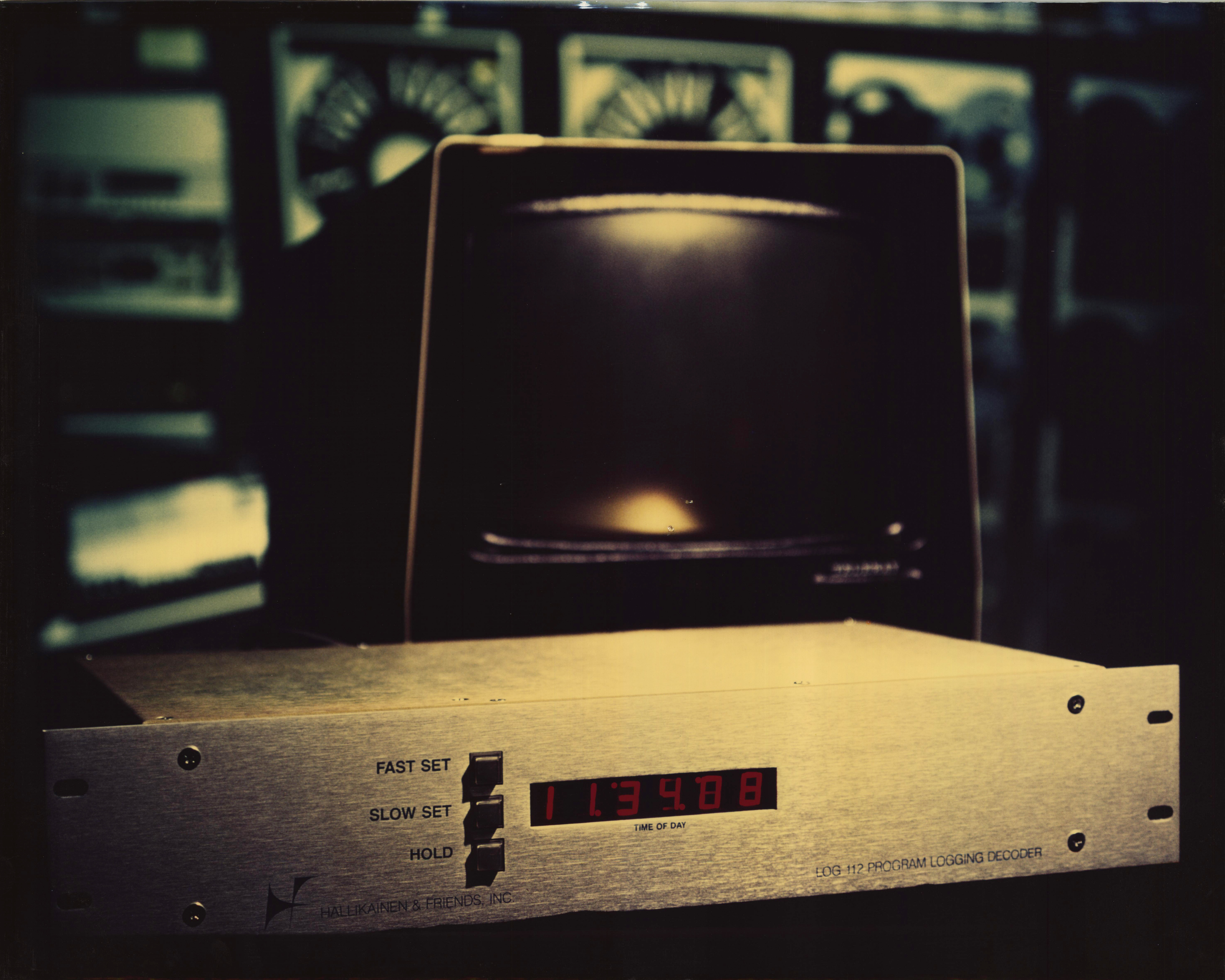
The program logging system in front of a Broadcast Products AR-2000 automation system with 6 Sonomag Carousels and 6 Revox A77 reel to reel decks.
- Datasheet
- AN-7901, Application note describing use of the program logging system to meet FCC requirements.
- Audio ad
- Photo The LOG 112 and 121 decoder and encoder resulted in a printed program log for automated radio stations. This was the first H&F product. A Teleray CRT terminal (early systems used the Lear Siegler ADM-1 terminal) drove the encoder. The message to be encoded was keyed in to the terminal. When ready to encode a cart, the user hit the "send line" key on the terminal. The encoder started the cart machine, waited 500ms, then brought up a 3.5kHz FSK tone on the cue track of the tape cartridge (after the 1kHz stop tone). The encoder then waited another second, then told the terminal to send its line of data (drive CTS true). The data was FSK modulated onto the cue track of the tape cartride. When the terminal was done, it drove RTS false, and the encoder shut down its tone.
When the cartridge was played on air, the decoder detected the 3.5kHz carrier. The decoder then sent a carriage return, line feed, the current time, a space, an alarm code, and another space to the printer. It then enabled the decoded FSK from the cart to be printed. The result was a nicely printed log on a Teleype model 43 printer. The alarm code was a single alphabetic character (A through I). If a particular rear panel input was grounded, the alarm code would print (they were priority encoded, so only one would print). Printing would occur on either the detection of the 3.5kHz carrier or a change in alarm code. This was all done with TTL circuitry, a multiplexed BCD clock, and a UART (no microprocessor).
- ROM Coding - The LOG112 logging decoder used a clock with multiplexed BCD output. On detection of the logging carrier, the LOG112 would print a carriage return, line feed, the time, a space, an alarm code, and another space. It would then gate in the demodulated data from the tape cartridge. The ROM code did the conversion from BCD to ASCII, generated the other characters, and routed data accordingly.
- Display Board Schematic - As described above, the LOG112 used a clock chip with a multiplexed BCD output. The display board took this multiplexed BCD and drove LED 7 segment displays.
- LOG-113 Time Base Schematic - The logging decoder generally used the 60Hz line as its real time clock timebase. In some situations, however, this was not accurate (due to varying line frequency or excessive noise on the power line). For those situations, a crystal time base was provided.
- Power Supply Schematic
- Power Supply Component Placement - A large aluminum bracket carried heat from the regulators to the side of the cabinet.
- Encoding System Block Diagram - This drawing shows the interface between the logging encoder and a TapeTronics cartridge machine. A Lear Siegler ADM-1 terminal would drive the logging encoder. A batch send would drive the RTS line of the RS-232 interface high. The logging encoder would start the cart machine, wait a half second (for the stop cue to go by), then enable cue record on the cart machine. A steady carrier was recorded for about a second. This allowed the demodulator used in playback to have a stable carrier before data keying was started. It also allowed the time and alarm code to be printed before data from the tape cartridge arrived. When the one second had passed, the CTS line went true, telling the terminal to start sending data. When the terminal was finished sending, it would drive RTS false, causing the logging encoder to drop the cart machine out of cue record.
- Encoder System Block Diagram - Shows signal flow between terminal, encoder, and tape record machine (audio or video)
- Encoder Schematic - Control and FSK modulator
- Live Studio Block Diagram - This drawing shows how a logging decoder would be wired in a typical live studio with several tape cartridge machines.
- Encoder Connections - This drawing shows how to connect the logging encoder to a TapeTronics cartridge recorder.
- Tapetronics to Encoder wiring - This drawing shows how to connect the logging encoder to a Tapetronics record/playback cartridge machine.
- Tapetronics to Decoder Wiring - This drawing shows how to connect several Tapetronics cartridge players to the logging decoder.
- SMC Carousel to Decoder Wiring - This drawing shows how to connect an SMC Carousel cartridge player to the logging decoder.
- Decoding System Block Diagram - Shows equipment interconnection for playback.
- Logging Decoder demodulator schematic
- Loggind Decoder UART Section - This section sent a sequence of characters out the RS232 port. Some characters came from the addressable clock while others were locally generated.
- Logging Decoder Addressable Clock schematic - Selects a BCD digit from the multiplexed BCD output of the clock chip
- Logging Decoder Audio Switcher - This external audio switcher was generally not required, but if tapes rolled when not on air, this switch would keep them from being logged.
TAX161 Time Announcer
The TAX161 was a 1.75 inch rack mount cabinet full of CMOS logic and relays. It controlled two tape cartridge machines, one holding announcements of even minutes, the other holding odd minutes. When an automation system closed a start relay to run a time announcement, the appropriate cart was played and the EOM closure routed back to the automation. If a minute was not announced in a particular minute, the system advanced the cart so it would be correct the next minute.
- Datasheet
- Audio ad. T
- Power Supply Schematic
- TAX-161 Main PCB Schematic
- Connecting TAX-161 to Automation - Various connection methods are shown. The standard method is a dedicated automation input. The drawing also shows how to share an automation input between the TAX-161 and a music playback deck. The shared input configurations can be sequential or simultaneous. If sequential, the automation triggers the TAX-161, which then starts the music tape deck. The result is the time announcement followed by the start of the music. The second method is simultaneous. Both the time announcement and the music start at the same time. The time is announced over the music intro.
TEL-171 Digital Telemetry Adapter
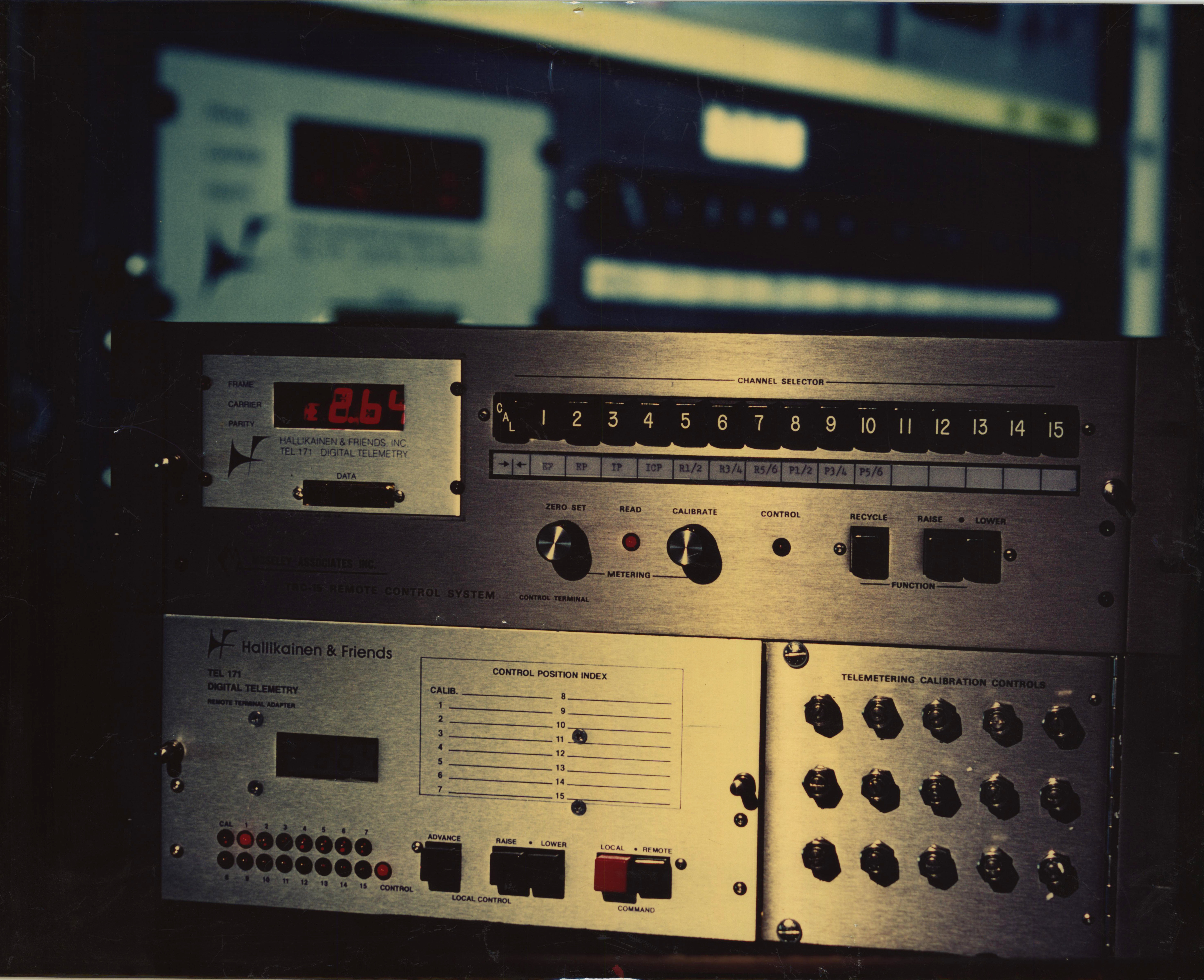
The TEL171 (introduced in 1977) is a set of four circuit boards that substitutes for circuit boards in the Moseley TRC-15A analog transmitter control system. The TEL171 converts the TRC-15A from analog to digital metering.
TRC-15A with TEL171 Teardown,
TEL172 Digital Telemetry Adapter
A set of boards that plugs into the Moseley PBR-30 to convert it to digital metering
Schematics
- 1391 Metering Demodulator - FSK demodulator and UART
- Studio Control Unit Metering Processor - Band pass filter for received metering FSK data.
- Studio Display. The TEL172 used an LCD for the studio display, while the TEL171 used an LED. When the TEL171 was designed, the LCD driver chip (7211) was not available. Later, the transmitter site display was designed for the TEL171. Less power was available to drive the transmitter site display and the 7211 had become available. So, the TEL171 ended up with LED at the studio and LCD at the transmitter. The TEL172, which worked with the PBR-30, was just the opposite. LCD at the studio and a small "calculator style" display at the transmitter.
- Transmitter Control Unit Metering Oscillator - This board replaced the original linear FM metering oscillator. The original was a linear FMO. The new one is an ADC driving an FSK generator.
- Transmitter Control Unit Audible Metering Processor - This FSK generator board replaced the original linear FM metering "processor."
- Midification of PBR-30 SCU Alarm Detector - Moseley PBR-30 alarm detector tripped on loss of telemetry tone. This modification made the timer retriggerable since it was driven by the demodulated FSK data. Loss of FSK data would trip the alarm.
- ITO-177 - This product was designed by Bill Bordeaux of Interstellar Communications. It provided a hardware and software interface to the Commodore 64 to make the TRC-15A/TEL-171 combination programmable.
ITO-178 Intelligent Transmitter Operator
This product was designed by Bill Bordeaux of
Interstellar Communications. It provided a hardware and software interface to the IBM PC to make the TRC-15A/TEL-171 combination programmable.PCC-180 Process Control Computer.
This was the predecessor to the DRC-190. It had a Basic interpreter and could emulate the studio end of a Moseley TRC-16, Moseley DRS-1, TFT 7601, or TFT 7610 control system. As with the DRC190, metering values could be evaluated in the Basic program and raise and lower commands could be sent. A typical command was DISPLAY METER(1,2). This would display the meter reading for site 1 channel 2 on the terminal screen.
- PCC-180 Battery Charger - The PCC-180 included a UPS. This charged the battery.
- PCC-180 I/O Board - This STD bus based board included the UART and AFSK modem to communicate with the transmitter site units. Another UART communicated with the local CRT terminal. A third UART and modem handled program storage on an audio cassette. Drawing is dated 14 July 1981. Another copy
- PCC-180 Installation Block Diagram - Shows connections to multiple transmitter sites and connection to audio cassette machine used for program storage.
- Site Select Board Schematic - This board would switch the remote control simulator to various phone lines. Unselected sites were looped through to the studio end of the remote control.
- I/O Board Schematic - This board emulated the studio end of a Moseley DRS-1, TRC-15A, or a TFT 7601 or 7610 remote control. Each of these systems used USRT data over FSK. The boards were loaded differently to handle the different FSK tones. The board sat on the STD bus in the PCC-180 for processor control.
TVA Series Audio Mixers
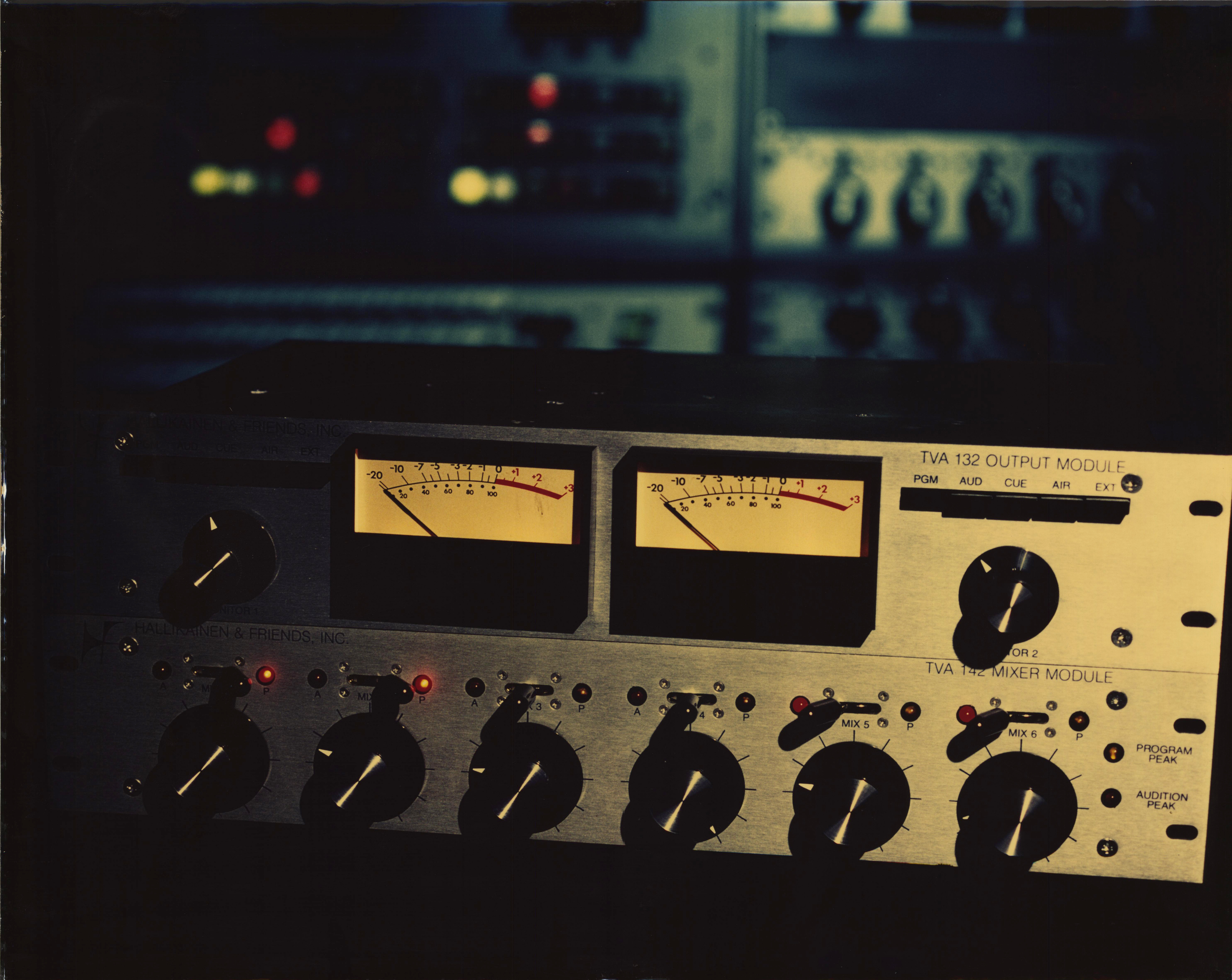
The TVA-132 and TVA-142
- Datasheet
- Early TVA series Datasheet
- Early TVA Series Datasheet - This includes the TVA-151 microphone preamp module that was never produced.
-
- Addendum increasing microphone input gain by 20 dB
- photo 4.4M
TVA-131 Output Module with balanced line monitor outputs
TVA-132 Output Module with monitor power amplifiers
- TVA-132 Power Amp Power Supply Schematic - A separate power supply drove the monitor power amplifiers in the TVA-132.
- TVA-132 Adjustments - These trimmers set various gains and meter sensitivity.
- TVA-132 Main PCB Component Placement
- TVA-132 Main PCB Schematic
- TVA-132 Power Amplifier Component Placement
- TVA-132 Power Amplifier Schematic
- TVA-132 Power Amplifier Power Supply Schematic
- TVA-132 Power Amp Power Supply component placement
TVA-142 Mixer Module
- TVA-142 Switch Locations - These switches allowed each input to be configured as a microphone or line level input.
- TVA-142 Main PCB Component Placement
- TVA-142 Main PCB Schematic
- TVA-142 Crosstalk Reduction Kit - Replaces LDR channel switching with reed relays to improve off channel attenuation.
- TVA Power Supply Sechematic - Three output regulated supply used in the TVA 132 and 142.
- TVA Power Supply Component Placement - This drawing shows the components in the universal power supply used in the TVA-142 and TVA-132.
- Sescom 66JD120 custom wound audio input transformer for TVA-142 and TVA-132.
NAB
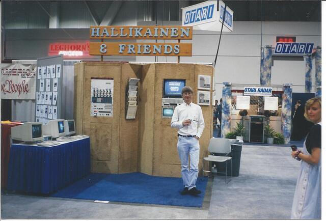
H&F exhibited at NAB for about 20 years. Here's a photo of the booth from about 1990. The table at the left holds CRT terminals for the various remote control and computer systems. The left rack has a DRC-299 (blank rack panel with 3.5 inch floppy drive on right), two TVA-142 audio mixers, a DRC-190 transmitter control system, a Moseley TRC-15A transmitter site unit with a TEL-171 digital adapter, and at the bottom the TRC-15A studio unit with the TEL-171 adapter. The right equipment rack holds video equipment to demonstrate Election Central. Election Central was election software for television stations. It gathered election data and drove a chracter generator for the on-air presentation of election results. Election Central was written by James (Jane) Brodsky.
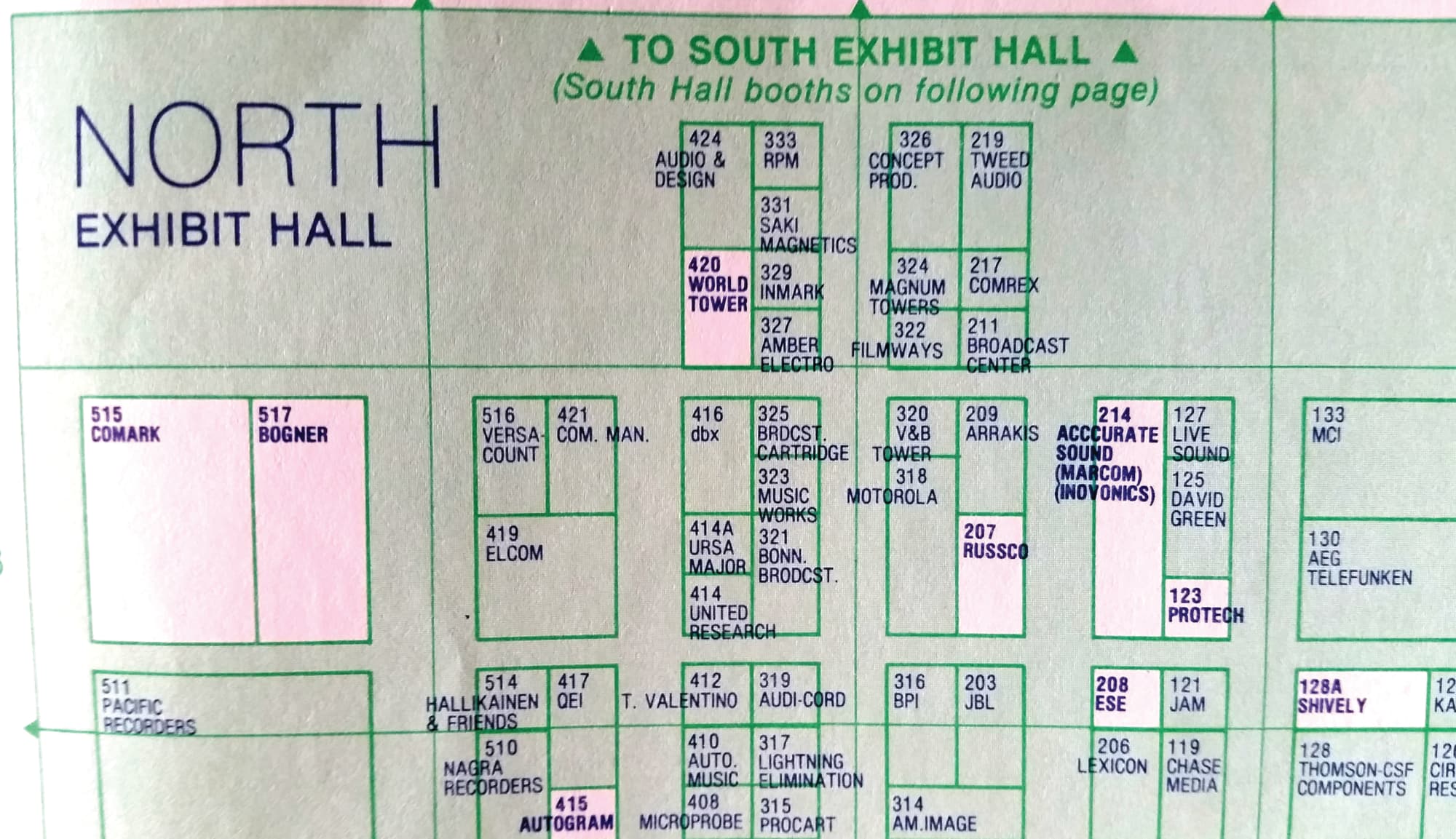
- 1981 NAB North Hall Map - Find us in booth 514!
 1981
1981
Back to HomePage
Contribute Documents?
