RCA
RCA
Company History
 David Sarnoff Library The David Sarnoff Library documents David Sarnoff's life; the history of radio, television, electronics, and communications; and the history of the Radio Corporation of America (RCA).
 RCA - an historical perspective discusses RCA from its formation in 1919 through 1976.
Manuals, Catalogs, etc.
- Antennalyzer analysis of directional arrays using analog techniques
- RCA Broadcast Transmitters - Provides support and manuals for RCA transmitters.
- Ampliphase For Economical Super Power AM Transmitters describes the theory of RCA Ampliphase modulation
- Broadcast News Number 1, October 1931. Includes articles on KFI, Los Angeles, Microphone Placement, Coverage Measurements using a new field strength meter, and a description of a police radio system. Original courtesy of Tom Friedman. 8.756M. An extensive collection of RCA Broadcast News is at American Radio History
- Principles of Operation of the Ampliphase Transmitter
- Radio Service Business Methods, John F. Rider and J. Van Newenhizen, 1936. How to make money fixing radios! 20 MB
- 1939 Broadcast Equipment Catalog
- RCA Broadcast Audio Equipment, 1967
- RCA Broadcast Audio Equipment, 1974
- RCA Broadcast Transmission Line Equipment for Television, 1957, including November 1, 1957 price list
RCA Ham Tips - Also see
 https://worldradiohistory.com/RCA_Ham_Tips.htm , http://n4trb.com/AmateurRadio/RCA_Ham_Tips/rca_ham_tips.htm , https://archive.org/details/rcahamtips1303/rcahamtips0101/ .
- May 1955 - 144 Megacycle Transmitter. 72 watts input on 144 Mc with an RCA 5894
- August 1955 - 144 Megacycle Transmitter. Part 2: Operation and adjustment
- December 1955 - A Secondary Frequency Standard
- July - August 1956 - Versatile Modulator.
- September 1956 - The Make Your Own Microphone
- April 1957 - RCA Publications for Hams, Longer life for 6146 and 866-A, A Conelrad circuit.
- April 1958 - A Transistorized Grid Dip Meter.
- June 1958 - A Transistorized Grid Dip Meter, part 2. Longer life for your 6146 beam power tube.
- February 1959 - The Weekend Special: A complete 40 meter CW station.
- August 1959 - For SSB Service: Cathode Driven Linear Amplifier Using RCA 7094 Beam Power Tube
- January - February 1960 - A Twp Transistor Regenerative Receiver for 80 and 40 meters
- May 1960 - A Low Cost, One Tube Walkie Talkie with transistorized audio stages.
- Summer 1962 - A 120 Watt 50 MC Transmitter.
- Winter 1962 - 1963 - A Mobile 50 Watt Transmitter for the Six and Two Meter Bands, Part 1
- Spring 1963 - A Mobile 50 Watt Transmitter for the Six and Two Meter Bands, Part 2
- Summer 1963 - Ham Band Charts, covering FCC allocations from 1.8 to 450 Megacycles
- Fall 1963 - A Low Noise UHF Transistor Amplifier
- Winter 1963 - 1964 - 300 Watt Output 432 Mc Amplifier, Utilizes RCA 8122 for class C operation
- Summer 1964 - A Low Cost High Efficiency Modulator. This is an interesting circuit. The modulator operates class A. A TV power transformer is used as a modulation transformer. Power is fed to the center tap of the HV winding of the transformer. One end of the HV winding goes to the plate of the modulator tube. The other end goes to the class C RF amplifier. Since the DC current of the modulator tube and the RF amplifier are about the same, the DC current in the transformer is balanced, thereby avoiding core saturation. The voltage to the RF amplifier is boosted a bit by putting the 5V winding in series. The 6.3V winding is used to provide negative feedback, reducing distortion. In addition, bias to the modulator is varied to reduce tube dissipation in the absence of audio.
- Fall 1964 - A 144 Mc Antenna Matching Preamplifier
- Fall 1965 - Paralleled Nuvistors on 220 Megacycles
- Winter 1965 - 1966 - All Transistor Two Meter Converter
- Fall 1966 - A Solid State AM Transmitter for Two Meter Operation
- June 1967 - A Power Supply for Transistor Circuits
- August 1967 - A VFO Calibrator
- October 1967 - Using a MOS Field Effect Transistor as a Product Detector and AGC Gate
- February 1968 - RCA Silicon Plastic Transistors in a Regulated TC to DC Converter
- July 1968 - An Audio Control System for SSB
- November 1968 - A Dual Gate MOSFET Preamplifier for the 10 Meter Band
- December 1968 - A Single Gate MOSFET Preamplifier for the 2 Meter Band
- May 1969 - Ham Band Charts: Covering FCC allocations, sub-allocations, and authorized emissions from 3.5 to 450 MHz
- November 1969 - A Precision Three Mode Voltage Calibrator
- December 1969 - A Magnetic Tape Keying System for Code Recording and Transmission
- January 1970 - Ham Band Charts (Phase Two), Covering FCC allocations, sub-allocations, and authorized emissions from 3.5 to 450 MHz
- August 1970 - 2 and 10 Meter Band Transceiver. A practical simplified approach to module package construction.
- RCA Picture Tubes - Characteristics and replacement directory. 1955
- RCA Power Tubes catalog PG-101F, 1963
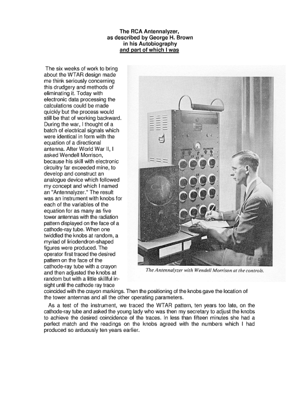 Antennalyzer
*1937 Transmitting Tube Handbook
*
- Radiotron and Broadcast Station List from 1929. From http://www.coutant.org/radiotron . 9.2MB
- RCA Receiving-Type Tubes for Industry and Communications. Catalog RIT-104. 1955. 9MB
- 40-C - The 40C Program Amplifier was RCA's first AC powered Program Amplifier. It seems to date from 1933-4. A contemporary of the 44A Velocity Microphone & 41B Pre-Amplifier. Scanned and contributed by Timothy Hughes. 2.9MB
- 41-B Microhpone Preamplifier (1935). Designed as a companion to the 44A microphone. Approximately 150 of an earlier version installed in NBC's Radio City. Scanned and contributed by Timothy Hughes. 2.4MB. 1.5MB.
- 44-A Velocity Microphone. 1933. Scanned and contributed by Tim Wright. 50MB.
- 55A - 55A Line Amplifier is physically and electrically similar to the 40C, but seems to be somewhat rarer. Scanned and contributed by Timothy Hughes. 2.8MB
- 56-E dual telephone line equalizer. 2 equalisers as a rack mounting unit. Listed in RCA 1950 Broadcast Equipment catalogue, p80. MI-4162 Black $32.50 US 1950, MI-4162-A Umber Gray, $40 US 1950. Scanned and contributed by Timothy Hughes.
- 58-A Tri-Amplifier (MI-4151). 3 input microphone mixer. 1936. Scanned and contributed by Tim Hughes. 5.7MB
RCA 69-C Distortion and Noise Meter
- 70-B transcription turntable. Approx. 1938-1939. Scanned and contributed by Timothy Hughes. 4MB
- 70-C2 Transcription Turntable illustration. The 70-C2 is a transcription turntable for reproducting both lateral- and vertical-cut records. A high torque snchronous motor provides 78 and 33 1/3 rpm turntable speeds. The pickup head is of the moving-conductor type with a diamond point stylus. The pickup and filter reporoduce various types of records with a response characteristic considered an ideal playback response. From Broadcast Operator's Handbook by Harold E. Ennes. John F. Rider Publisher, Inc. 1951. Contributed by Tim Hughes. 1.5MB.
- 70-D transcription turntable. More info at http://www.coutant.org/rca70d/index.html
- 76-B2 Consolette. Scanned by Lane Lindstrom. 3MB.
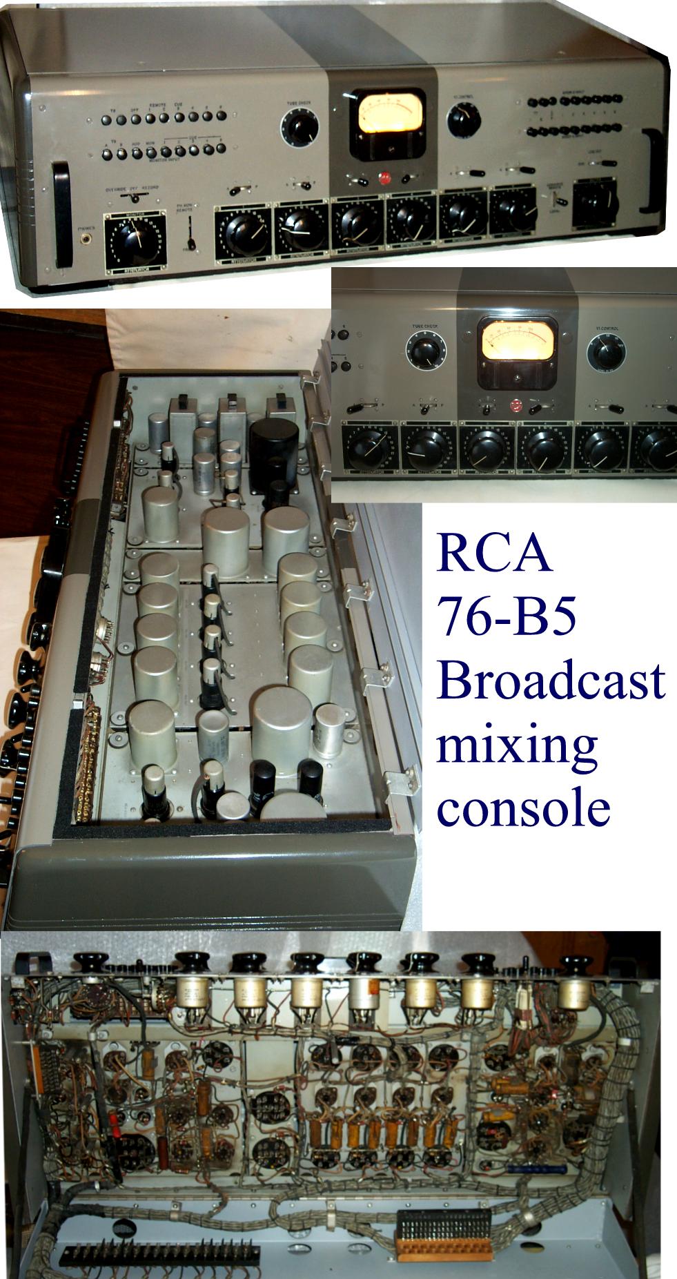
- 76-B5 Audio Console photo
76-C Console
- 82-A Monitoring Amplifier. This model appears to be the genesis for a range of Photophone and PA amplifiers. Scanned and contributed by Timothy Hughes. 3MB
- 83-C Isolation Amplifier. The Type 83-C isolation amplifier has been designed especially for broadcast speech input installations as a line bridging amplifier, but it can also be used as a monitoring amplifier where large outputs are not required. Scanned and contributed by Timothy Hughes. 2.1MB
- 85-B1 Microphone Preamplifier. Scanned and contributed by Timothy Hughes. 1.8MB
- 86-A1 Limiting Amplifier schematic From Broadcast Operator's Handbook by Harold E. Ennes. John F. Rider Publisher, Inc. 1947. Contributed by Tim Hughes. 245kB.
- 94-C amplifier. Industrial design by John Vassos. Response tailored to complement Harry F. Olson's UZ-4209 dual voice coil speaker and 64-A Monitoring Speaker. The peak of RCA amplifier design before the 6L6 with feedback displaced triode output stages. Scanned and contributed by Timothy Hughes. 2.3MB
- 158 Cathode-Ray Oscillograph, 1943.
- 160-B Cathod-Ray Oscillograph. 1943.
- BA-1A two stage preamp. Scanned and contributed by Tim Wright.
- BA-2A Booster amplifier. 1 MB.
- BA-3A program amplifier. 5 MB.
- BA-4A Monitoring and recording amplifier. 3 MB.
- BA-4C monitoring and recording amplifier. Scanned and contributed by Tim Wright. 24.6MB
- BA-13A Program amplifier. 4 MB.
- BA-23A Program Amplifier. Reported to be first produced in late 1954. Listed in RCA Broadcast Audio Equipment for AM FM Television, 3rd (1957), 4th (1959) and 5th (1963) editions. $204.75 US 1963. Contributed by Timothy Hughes. 9.2MB
- BC-3C Standard Consolette. Contributed and scanned by Lane Lindstrom. File size: 3.7MB. Another Copy, another copy
- BC-7A Stereo / Dual-Channel Consolette. Contributed and scanned by Lane Lindstrom. File size 3.8MB
- BN-2A portable remote amplifier. Scanned and contributed by Tim Wright. 25.2MB
- BTA-1N1 1kW AM transmitter, product brochure. Uses 3CX3000F1 operating as a class AB1 linear RF final amplifier. Scanned by John T. M. Lyles.
- BTA-1L 1kW AM transmitter. Contributed by Scott Todd. 1946. 14M
- BTA-1R Reduced Size (32.1MB), scanned and contributed by Mike McCarthy
- BTA-1R Full Size (189MB), scanned and contributed by Mike McCarthy
- BTA-1R1 1kW AM transmitter. Scanned by Stanley Adams
- BTA-1R3 Reduced Size, scanned and contributed by Mike McCarthy
- BTA-1R3 Full Size (240MB), scanned and contributed by Mike McCarthy
- BTA-1S1 1kW AM transmitter, product brochure. Scanned by John Lyles.
- BTA-10F 5 or 10 kW AM transmitter, manual. Shared by Scott Todd and scanned by Stanley Adams.
- BTA-50H 50kW Ampliphase Transmitter product introduction
- BTA-250L Broadcast Transmitter is a complete, self-contained unit that will provide reliable, high-fidelity operation at any frequency within the range of 540 and 1600 kc. Excellent frequency stability is attained by the use of a crystal contained in a temperature-controlled chamber in the oscillator circuit. No greater deviation than +/- 10 cycles from the assigned operating frequency is pemitted. Contribued by Scott Todd. 29M
- BTA-250M Broadcast Transmitter is a complete, self-contained unit that provides a power output of 250 watts at any frequency in the 535 to 1620 kilocycle range. Mounted in a single RCA Type BR-84 steel cabinet, the unit utilizes a temperature-controlled crystal for close regulation of the operating frequency. Contributed by Scott Todd. 8.6M
- BTE-10C FM Broadcast Exciter and BTE-10C FM Broadcast Transmitter. Contributed by Scott Todd. 5M
- BTE15A less schematics]. Scanned and submitted by Michael Dinger 12M
- FTF-1D 1kW FM transmitter. Article from March 1960 issue of RCA Broadcast News describing this new transmitter.
- BTF3B FM Broadcast exciter and transmitter, very popular unit with Reactance tube modulation and tuning motor to control the AFC of division stages. "Iron Fire Man" Exciter. Manual by Dave Hultsman and scanned by Stanley Adams. This short description if of the exciter, from our friend Don Wilson. RCA-MI7106 Exciter
- BTF-10C - Article from March 1960 issue of RCA Broadcast News describing this transmitter.
- BTF-10D 10kW FM Broadcast Transmitter. About 1962. 36MB
- BTF-10D 1962, 17MB
- BTF-20E1 20 kW FM transmitter. 1969
- BTF-40E1 40 kW FM transmitter. Combines a pair of BTF-20E1 transmitters. 1978.
- BTP-1A Broadcast Transmitter schematic. From Broadcast Operator's Handbook by Harold E. Ennes. John F. Rider Publisher, Inc. 1951. Contributed by Tim Hughes. 147kB.
- BTS-1A Stereo Subcarrier Generator. Contributed by Scott Todd. 4M
- BW-66F AM modulation monitor. Scanned and contributed by Alan Kline. 24M
- BX-1A preamplifier power supply. 1 MB.
- OP-6A Portable Amplifier. MI-11202/A. 250 ohm input, 1620 input stage with variable feed-back as part of the gain control, 2 stage 1620 main amplifier with output anode to input cathode feedback. Output jumperable between 150 and 600 ohms. VU meter, 6X5GT/G rectifier. Provision for battery Supply. Schematic (370k) from The Radio Manual, Sterling & Munro. 4th edition 1950. Contributed by Tim Hughes.
- OP-7 Portable Mixer. MI-11213. Used with OP-6 amplifier. 4 x 30/250 ohm mic inputs, 1620 pre-amps triode connected, 250 ohm low level output. 6X5GT/G rectifier. Provision for battery Supply using MI-11214 Battery Box. Schematic from The Radio Manual, Sterling & Munro. 4th edition 1950. Contributed by Tim Hughes.
- TM-10A Color Video Monitor
*Article from Jan/Feb 1954 issue of RCA Broadcast News discussing this monitor.
- TMV-75B Field Strength Meter (500 kHz to 20 MHz). Includes certificate of calibration from National Bureau of Standards dated March 21, 1941. Includes a schematic of modifications for driving a chart recorder dated April 3, 1936. Contributed and scanned by Willis (Bill) Frahm, bill.frahm@citcomm.com.
- TMV-128-A Frequency Modulator
TT FL Line of VHF Television Transmitters
- Volume III - Operating Instructions, 72 MB
TT-30FL VHF TV Transmitter (30 kW, channels 2 through 6)
- Installation Instructions, IB-8027540. 10 MB
- TF-12AH Superturnstile Antennas
- WX-2A Field Strength Meter. Scanned by Dale H. Cook. 25.5MB
 photo
photo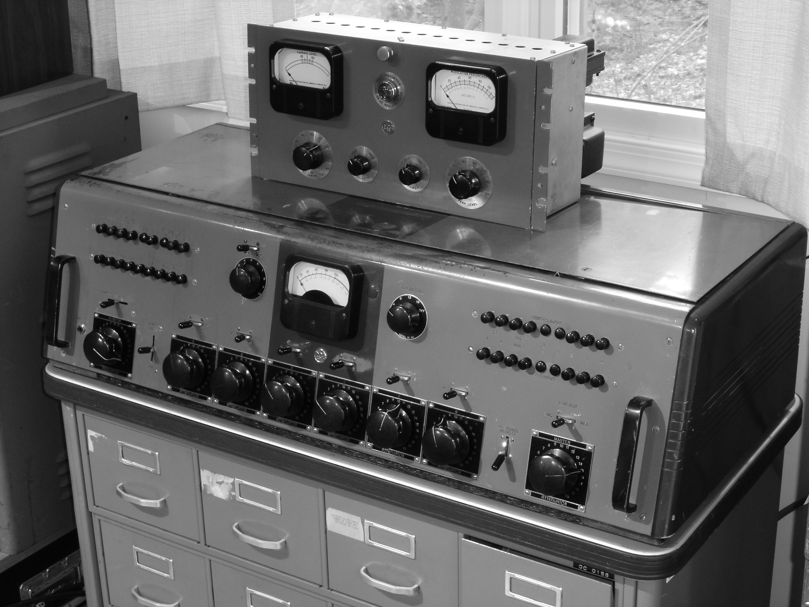 Photo
Photo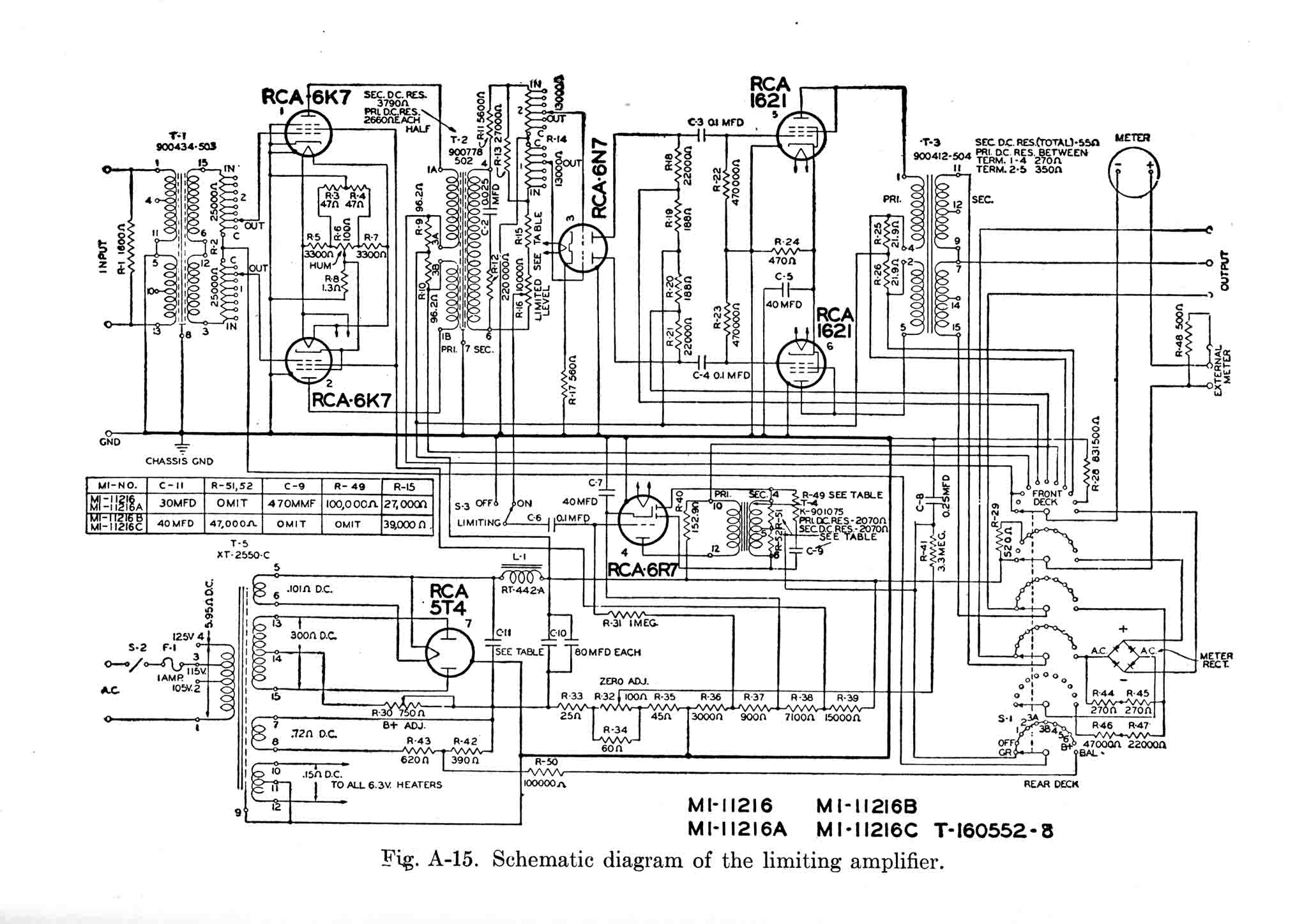 schematic
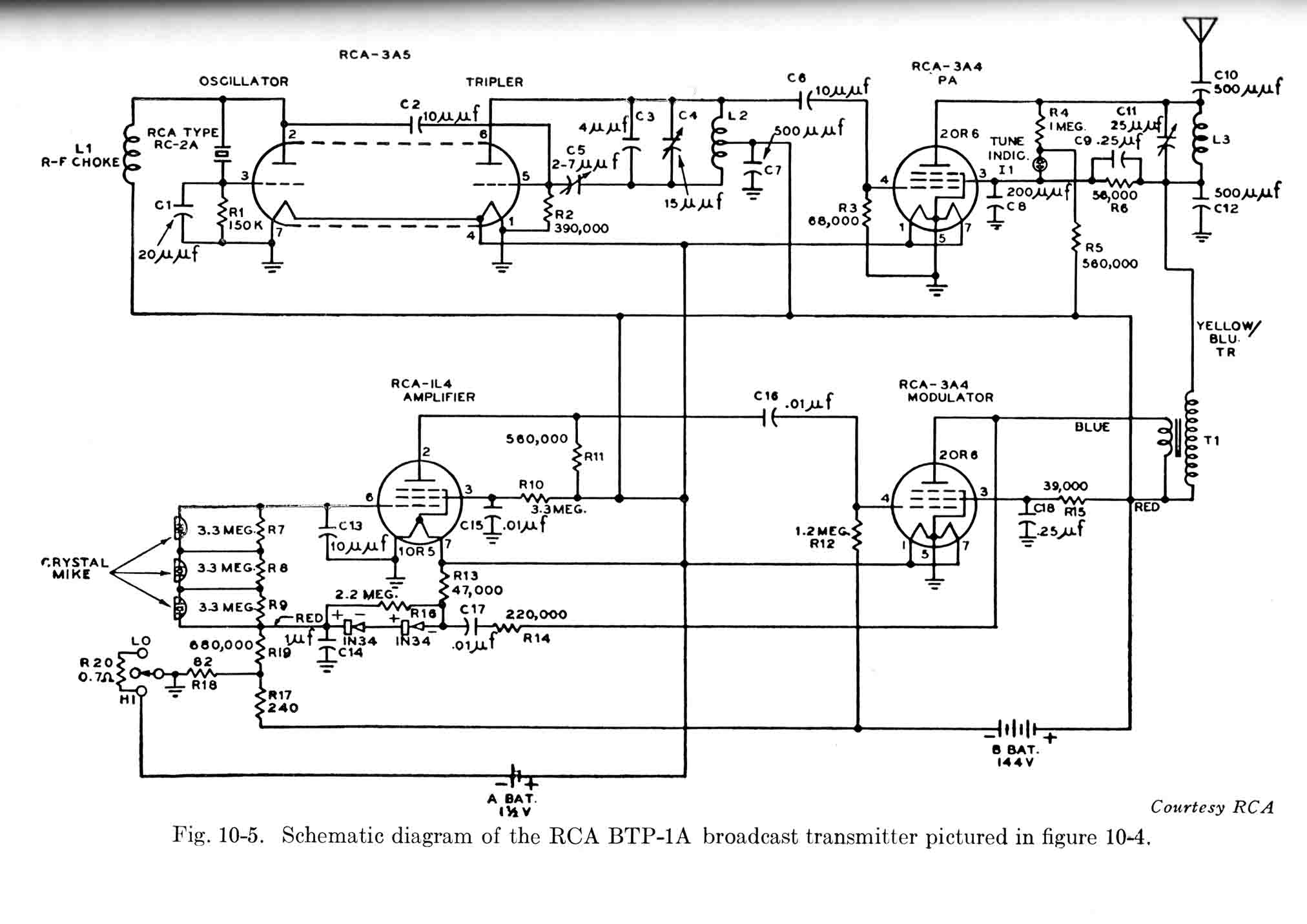 schematic
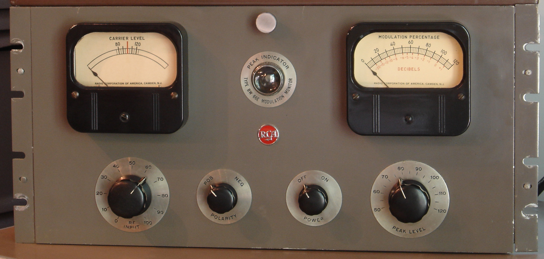 Photo
Photo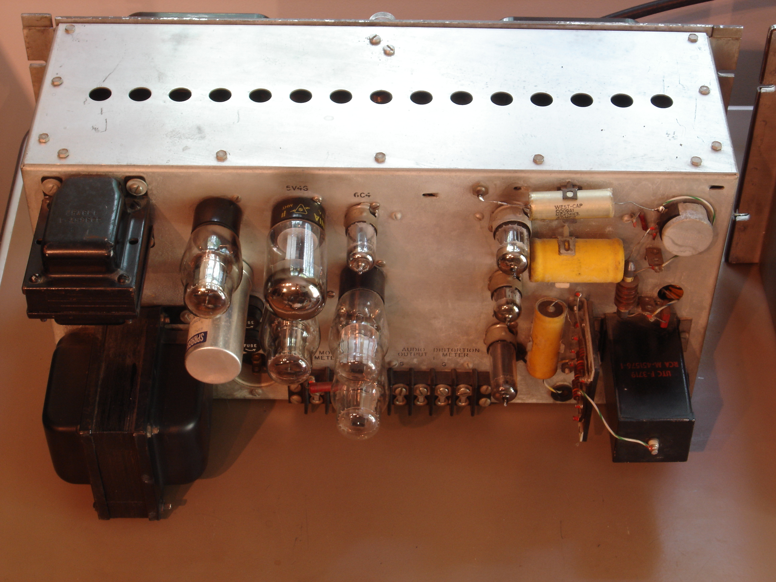 Photo
Photo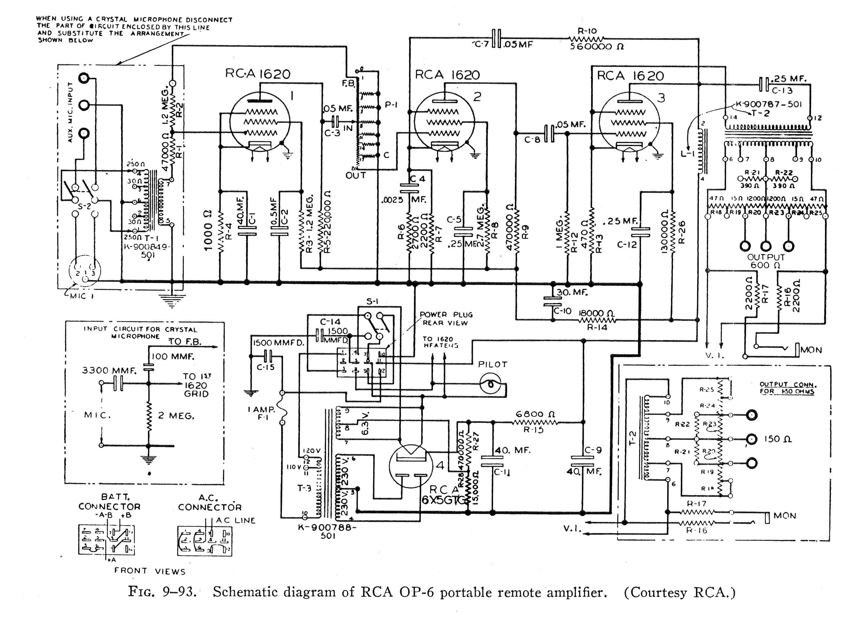 Schematic
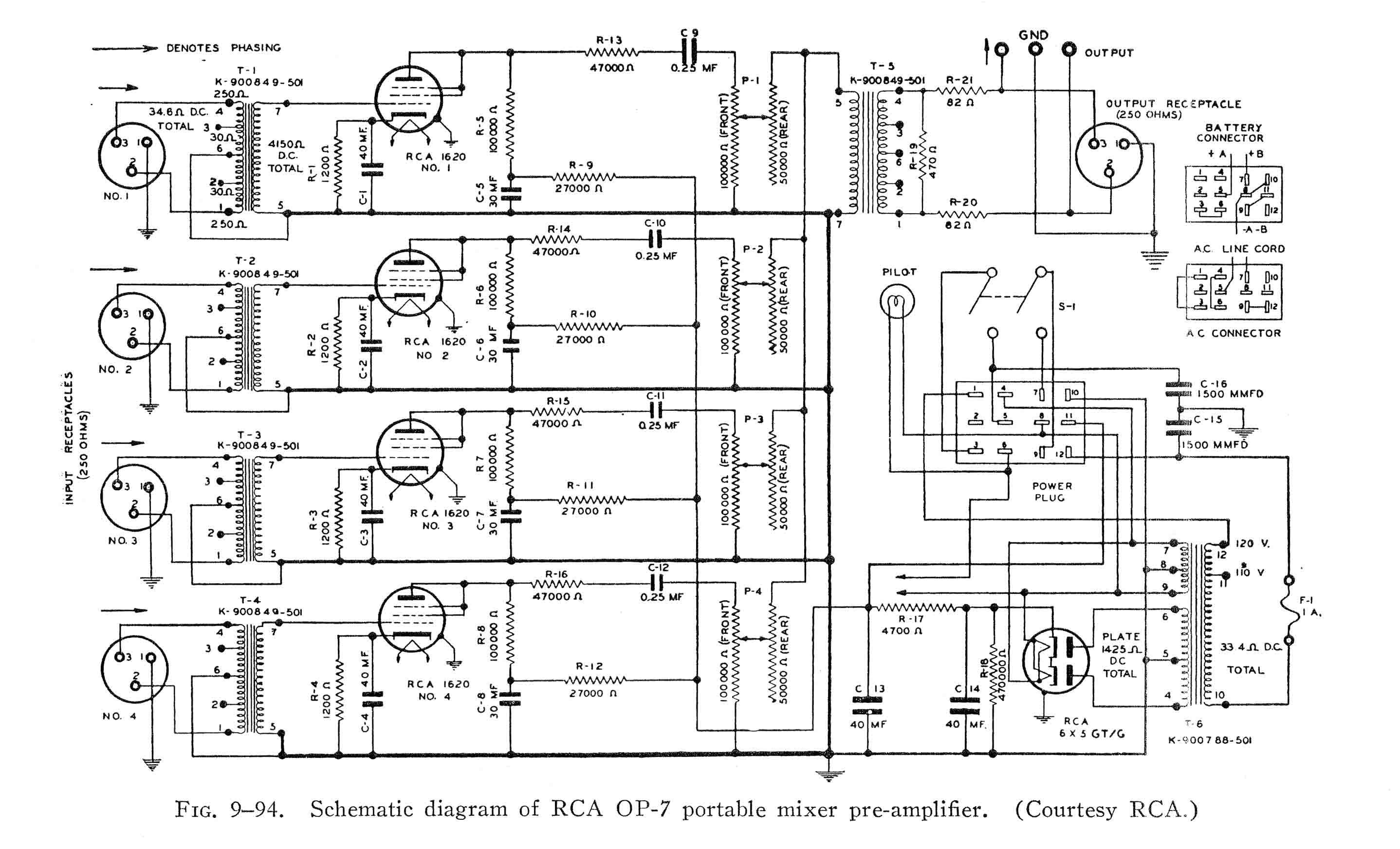 Schematic
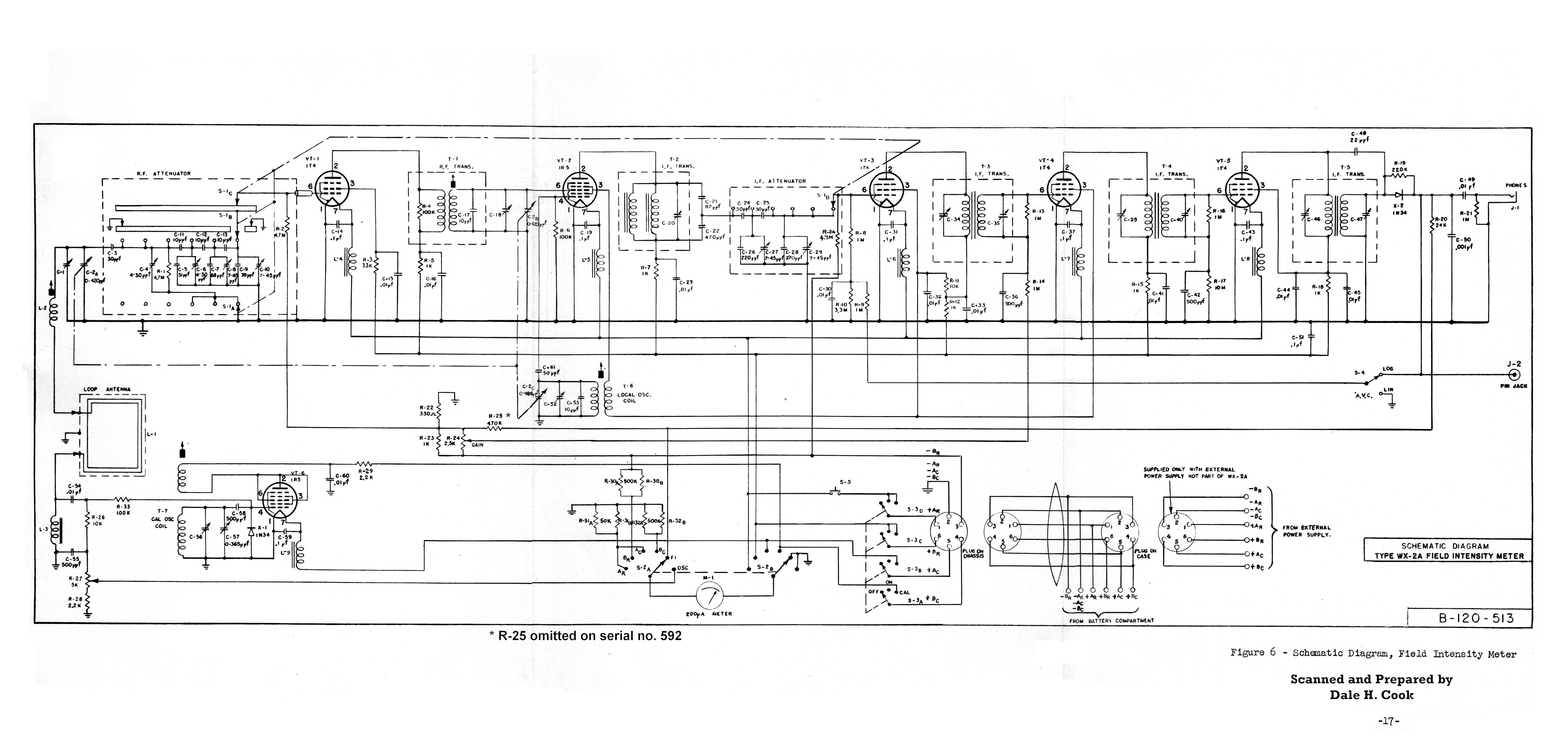 Schematic
Outside Resources
The following excellent sites have large collections of RCA data.
- RCA Documentation at One Electron. EXTENSIVE collection of RCA Bulletins, Notices, Application Notes, articles, etc.
- RCA HB-3 Tube Manuals at Tube Books
Back to HomePage
Contribute Documents?
