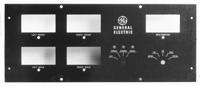
General Electric Quadraphonic
Four channel discrete quadraphonic equipment by GE In December of 1972, Moseley Associates was approached by General Electric to built a four-channel stereo generator to spec. As might be expected, there was a contract spelling out responsibilities, non-disclosure agreements, extensive mathematical analyses, rationale for the approach taken and a very extensive set of photographs of oscilloscope traces of the waveforms involved.
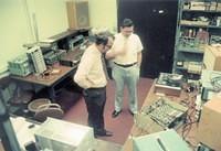
Moseley agreed to do the project. Personnel on the project included, from GE, Antal “Tony” Csicsatka, Leslie “Les” String and Henry P. Lee. Personnel from Moseley Associates included Howard Ham and Jim Tonne (ye scribe).
There was considerable communication between GE and Moseley and a working four-channel (“Quad”) generator was finalized in June of 1973. It was based on the GE concept of “sum-and-difference” signals.
In the case of two-channel stereo, the two input signals are summed and form the “main channel” signal. This signal modulates the transmitter as in monaural operation. The two input signals are subtracted, used to modulate a double-sideband suppressed-carrier modulator with a virtual (suppressed) carrier at 38 kHz. The resulting subchannel signal also moduates the transmitter.
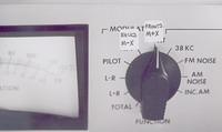
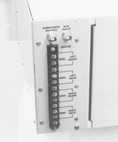
In the case of four-channel stereo a similar set of processes is involved. However there are two balanced modulators at 38 kHz with their carriers in quadrature and another balanced modulator at 76 kHz. Unique with the GE system was the operation of the 76 kHz signal in the vestigial (lower) sideband mode. The output from the 76 kHz balanced modulator was applied to a filter which passed the lower sideband along with only that portion of the upper sideband which is near the carrier frequency. From a practical viewpoint this upper channel was operating single-sideband. The rationale was that this would reduce bandwidth requirements in the receiver and would allow SCA operation as in the two-channel stereo system; the SCA subcarrier would reside at 95 kHz.
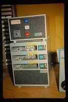
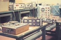
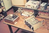
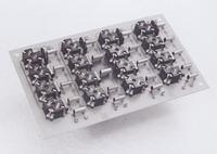
That upper channel filter basically dictated the operation of the system in terms of time delay. Although each of the balanced modulators was operated in a linear mode (as opposed to switching) they all had to end up at a summing point at the same time. Hence a good part of the design effort was spent on designing delay lines. It is unfortunate that no photos were taken of this aspect of the generator. In the photo looking down on the generator during testing, the upper-level deck is full of the electronics. The bottom side of that same plate is full of bandpass filters and delay line components.
The technical description of this system is shown in Mr. Csicsatka’s patent, 3934092, dated December of 1972. By the way, the original stereo patent is also by Mr. Csicsatka, and is numbered 3122610, dated July 1960.
I took some photos of this system as it was being built. Let’s look at them.
Moseley agreed to do the project. Personnel on the project included, from GE, Antal “Tony” Csicsatka, Leslie “Les” String and Henry P. Lee. Personnel from Moseley Associates included Howard Ham and Jim Tonne (ye scribe).
There was considerable communication between GE and Moseley and a working four-channel (“Quad”) generator was finalized in June of 1973. It was based on the GE concept of “sum-and-difference” signals.
In the case of two-channel stereo, the two input signals are summed and form the “main channel” signal. This signal modulates the transmitter as in monaural operation. The two input signals are subtracted, used to modulate a double-sideband suppressed-carrier modulator with a virtual (suppressed) carrier at 38 kHz. The resulting subchannel signal also moduates the transmitter.
In the case of four-channel stereo a similar set of processes is involved. However there are two balanced modulators at 38 kHz with their carriers in quadrature and another balanced modulator at 76 kHz. Unique with the GE system was the operation of the 76 kHz signal in the vestigial (lower) sideband mode. The output from the 76 kHz balanced modulator was applied to a filter which passed the lower sideband along with only that portion of the upper sideband which is near the carrier frequency. From a practical viewpoint this upper channel was operating single-sideband. The rationale was that this would reduce bandwidth requirements in the receiver and would allow SCA operation as in the two-channel stereo system; the SCA subcarrier would reside at 95 kHz.
That upper channel filter basically dictated the operation of the system in terms of time delay. Although each of the balanced modulators was operated in a linear mode (as opposed to switching) they all had to end up at a summing point at the same time. Hence a good part of the design effort was spent on designing delay lines. It is unfortunate that no photos were taken of this aspect of the generator. In the photo looking down on the generator during testing, the upper-level deck is full of the electronics. The bottom side of that same plate is full of bandpass filters and delay line components.
The technical description of this system is shown in Mr. Csicsatka’s patent, 3934092, dated December of 1972. By the way, the original stereo patent is also by Mr. Csicsatka, and is numbered 3122610, dated July 1960.
I took some photos of this system as it was being built. Let’s look at them.

Album info
Available RSS feeds
Popular tags
Random image