Diff: WesternElectric
Note: You are viewing an old revision of this page. View the current version.
Differences between version 5 and previous revision of WesternElectric.
Other diffs: Previous Major Revision, Previous Author
| Newer page: | version 5 | Last edited on 25 December 2011 13:27 | by harold | Revert |
| Older page: | version 4 | Last edited on 29 December 2019 19:10 | by harold | Revert |
version 5
 Western Electric
*Other Sites
- http://www.audiosharing.com/archive/western/western.htm has extensive information on WE audio equipment, vacuum tubes, and receivers.
*AM Receivers
*
10A AM receiver schematic. 1934. 848k. Scanned by Stanley B. Adams
*AM Transmitters
- Technical Bulleting T-670, 1923. Describes the 101-A and 102-A radiotelephone broadcasting systems. The 101-A uses a 1-A 500W transmitter. The 102-A uses a 2-A 100W transmitter. Each system includes motor-generator power supply, 1A speech input amplifiers, and 2-C radio receivers. The receivers are used to comply with radio regulations requiring periodic monitoring for distress calls. Scanned and comtributed by Timothy Hughes. 8MB.
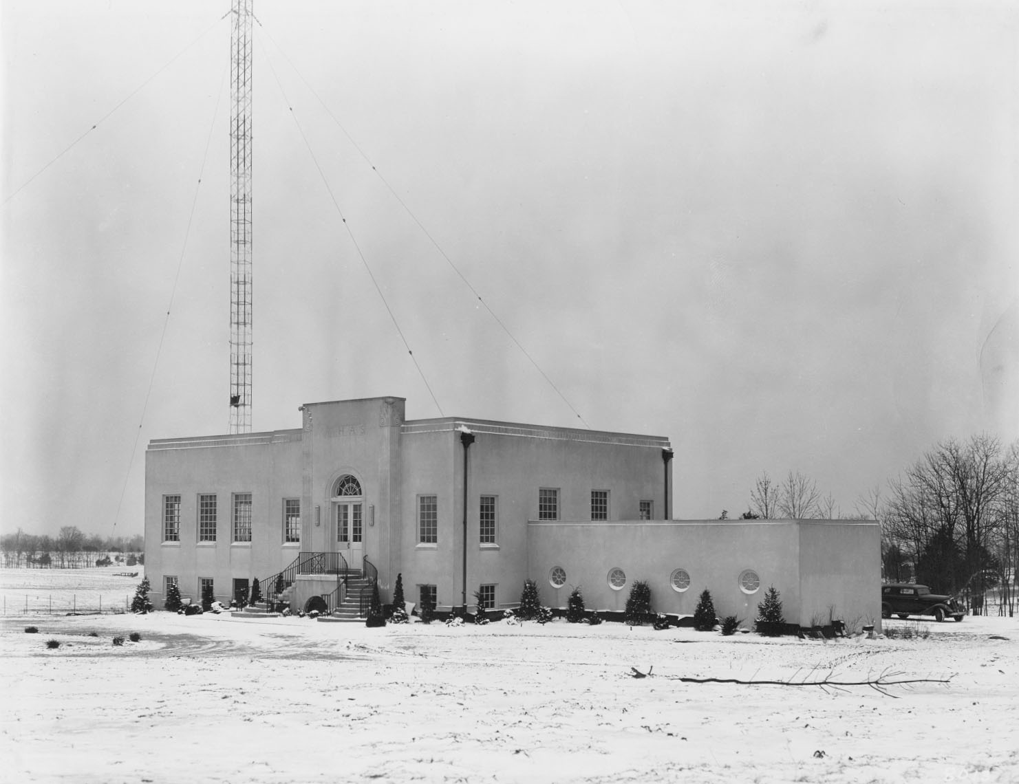
- The DOHERTY Amplifier - Approx 1942. Booklet describing the Doherty amplifier. Gives a brief description of the theory behind the Doherty amplifier. Includes letters from WHAS, KTUL, KQW, and KRLD. Contributed by Randy Kerbawy. See also A New High-Efficiency Power Amplifier for Modulated Waves , Doherty's original paper on the Doherty method of generating AM. Additional photos of WHAS (as mentioned in the WE booklet) are available. These photos are posted by Scott Cason.
- Upload:WeEastwood.jpg - Transmitter building after it was completed in 1938.
- Upload:WeWhasXmtr.jpg - Photo of WE transmitter
- Upload:WeWhasTx.jpg - The WE transmitter being worked on
- http://www.qsl.net/wb4wsb/whasam/patubes.jpg - Closeup of final amplifier
- http://www.qsl.net/wb4wsb/whasam/xmtroom.jpg - Transmitter room with WE AM transmitter on left, control console in middle, FM transmitter on right.
- Upload:WeXmtrConsole.jpg - Close up view of transmitter control console
 Upload:
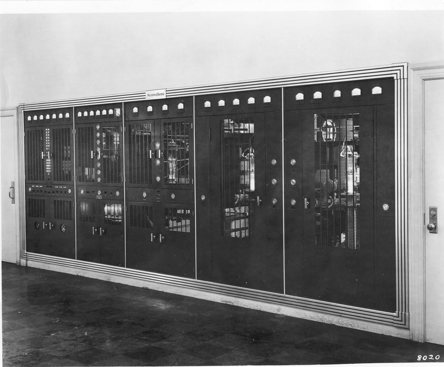 Upload:
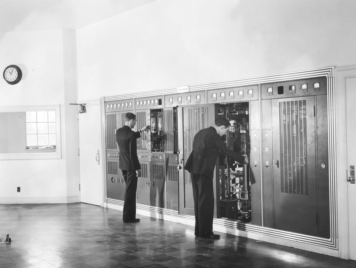 Upload:
 http://www.qsl.net/wb4wsb/whasam/patubes.jpg
 http://www.qsl.net/wb4wsb/whasam/xmtroom.jpg
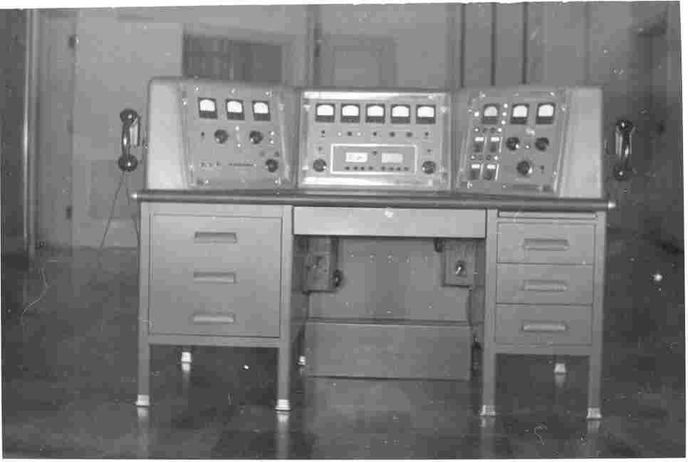 Upload:
** 23-A Western Electric Transmitter- 100 to 250 watt transmitter* for the 310-A or B series by Stanley B. Adams
** 106-A Radio Telephone Broadcasting Equipment - 1kw - October 1926* - Scanned by Stanley B. Adams.
**
**Continental Electronics 105C One Mega Watt Medium Wave Transmitter*. The Continental Electronics 105C very clearly shows the Weldon-Western Electric lineage. This is supposedly the first mega-watt medium wave transmitter in the world. While there are slight circuit differences and some tube differences, please note that this is a linear based transmitter that uses the Weldon modified Doherty circuit. This was supplied through the courtesy of David Hultsman of CCE and scanned by Stanley Adams. *
*Audio Equipment
- Western Electric Instruction Bulletin 903 - 22B, 22C, and 22D Speech Input Equipment. Scanned by Charles Ring.
- I126-A compressing amplifier. Scanned by Stanley Adams. 1.8M
*FM Transmitters
- 504A-1 Synchronized Frequency Modulation Radio Transmitting Equipment, 3000 Watts, 42 to 50 Megacycles. This brochure describes the 504A-1 FM transmitter that operated in the "original" FM band. Synchronized frequency modulation refers to the unique automatic frequency control.
"In synchronized frequency modulation, the total number of cycles is, in effect, counted, compared with the number of cycles generated by a precise fixed frequency standard, and the tuning of the variable oscillator adjusted mechanically to keep the two always at exactly the same value." The carrier is divided by 8,000 and compared with a 5kHz reference crystal oscillator.
One added note by Stanley Adams, this pre-war 'box' also served as the basic design when FM 'cranked up' after the end of WW2. The synchronizing circuit consisted of a motor that was modulated by the error voltage between a crystal standard and the 'countdown' chain. This would vary a capacitor in the exciter. A number of stations replaced this 'mistake' during the early 50's with units devised by companies such as Harkins Electronics of Phoneix, Arizona. This was a serrisoid type of exciter and much more stable.
*Vacuum Tubes
- Tubes for Telephone Broadcasting, late 1920s. Scanned by Stanley B. Adams
- Additional WE Tubes for Radio and Broadcasting, through mid 40's. Stanley Adams
- WE104-D vacuum tube triode. 1941. 3M. Scanned by Stanley B. Adams
- WE211 75 Watt Power Triode, 1936, scanned by Stanley B. Adams
- WE212E 275 Watt Power Triode, scanned by Stanley B. Adams
*Telecom
- L5 Coaxial Carrier System provides 10,800 4kHz message channels per coax pair. 1974. 15.8MB
Back to HomePage
Contribute Documents?
